DESCRIPTION - Light Emitted Diodes (L.E.D.) Edge Lit Internally Illuminated Street Name Signs.
This specification shall govern for L.E.D. Edge Lit Internally Illuminated Street Name Sign attached to the traffic pole or wire span, as recommended. All materials used in fabrication shall be new and of excellent quality. |
| WARRANTY, MAINTENANCE AND SUPPORT All manufacturers guarantees and warranties which are normally provided as customary trade practice for items and materials incorporated into the work. All materials have warranty including led and driver for (5) years. Housing:
-
The extrusion/housing is made from 6053-T5 aluminum and is 2 “X 2 5/8”.
Light engines are mounted inside the top channel by stainless steel screws.
The thickness of material where the screws are mounted is a ¼” thick. This will also help to
deflect the heat and rigidity. The other side of the extrusion are grooves to accept plastic faces.
The dimension on this is; 3/16” X ½“” deep. Plastic sits in the groves.
Sign Panels:
-
The entire surface of the sign panel shall be evenly illuminated .
-
The sign panels shall be translucent of high impact, UV resistant plastic/acrylic material able to
withstand 5 years of 500nm UV light. All surfaces shall be free of blemishes in the plastic and
coating that might impair the service or detract from the general appearance and color matching
of the sign.
Hardware:
-
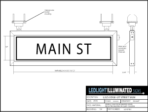
The sign can be mounted to a rigid mast and/or span wire.
-
All fasteners and screws in or on the fixture, shall be stainless steel type 302 or 305.
ELECTRICAL:
Light source: The L.E.D. Edge Lit Internally Illuminated Street Name Sign modules shall be composed of 1-watt L.E.D.’s with a minimum viewing angle of 20 degrees mounted on rugged metal boards consuming no more than 5 watts per linear foot. With a thermal resistance path from the L.E.D. to the most external surface of the aluminum extrusion, of no more than 20 degrees per watt at an ambient temperature of 25 degrees Celius to reduce wear and tear on the individual L.E.D.’s and to extend usuable lifetime. The L.E.D. light modules should be sufficient coupled directly to the aluminum extrusion using stainless steel mounting screws from top of extrusion. The light panel redirects the light to create a uniform illuminated panel with a minimum candelas per metered squared of 50 nits at initial turn on and no less than 15 nits after five (5) years. L.E.D. SYSTEM L.E.D. Housing: 1”x 48“ x ¼”Aluminum plate, Threaded mounted holes for #8 screw on back-side spaced every 10 inches. OPTICAL System: L.E.D. assembly shall have linear collimating optic with an emitting angle of 5x20 degrees +/- 5 degrees. The optic shall be manufactured of optically clear acrylic. The optic shall be sealed to the L.E.D. housing via a clear urethane. L.E.D. Assembly: The L.E.D. assembly shall consist of one (1) or multiple MCPCB (Metal Clad Printed- Circuit Boards), that are designed specifically to spread from high brightness L.E.D.s. The MCPCBs shall have a white solder mask and an aluminum substrate. L.E.D.s shall be Lumileds Luxeon L.E.D.s and shall be spaced 3” on center. The L.E.D.s shall be wired in series to promote even illumination. The L.E.D. assembly shall be designed such that multiple MCPCBs shall be plugged together to reduce wiring and connections within the L.E.D. housing. The L.E.D. assembly that is located at the end of the L.E.D. housing shall have 6” wire leads with water resistant faston connectors for ease of installation and replacement. L.E.D. assembly length shall be determined based on the overall length of the signs. Should the sign be approximately 8’ in overall length, (2) 48” L.E.D. system shall be used to provide illumination. Should the sign be approximately 4’ in overall length, ( 1) 48” L.E.D. system shall be used.
DRIVER SYSTEM The L.E.D. System shall be illuminated with a L.E.D.driver .
The Driver System shall consist of the following:
-
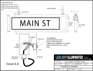
Driver Housing: The termination Housing shall provide waterproof sealing in the form of a gasket and cover. Wires shall enter the Driver via 1 Nylon Strain Relief. The termination Housing shall accommodate a built-in photocell that protrudes through the cover of the termination Housing.
-
Electrical: The Driver shall include the following:
-
AC to DC power supply: the power supply shall have a universal input voltage
(90 to 264VAC) and an input frequency range of 47 to 63 Hz. The power supply
output shall be 100VDC. The power supply shall be UL recognized and shall have TUV
and CE certifications.
-
The Driver System: In order to properly and safely illuminate the L.E.D. System,
multiple Drivers shall be soldered to a PCB (Printed Circuit Board), that is mounted
To the PCB. The PCB shall be wired and powered by the AC to DC
Power Supply. The Driver system shall provide a 250mA constant current.
|